- 您现在的位置:买卖IC网 > Sheet目录2003 > LTC1408IUH-12#TRPBF (Linear Technology)IC ADC 12BIT 600KSPS 32-QFN
15
LTC1408-12
140812f
APPLICATIO S I FOR ATIO
WU
UU
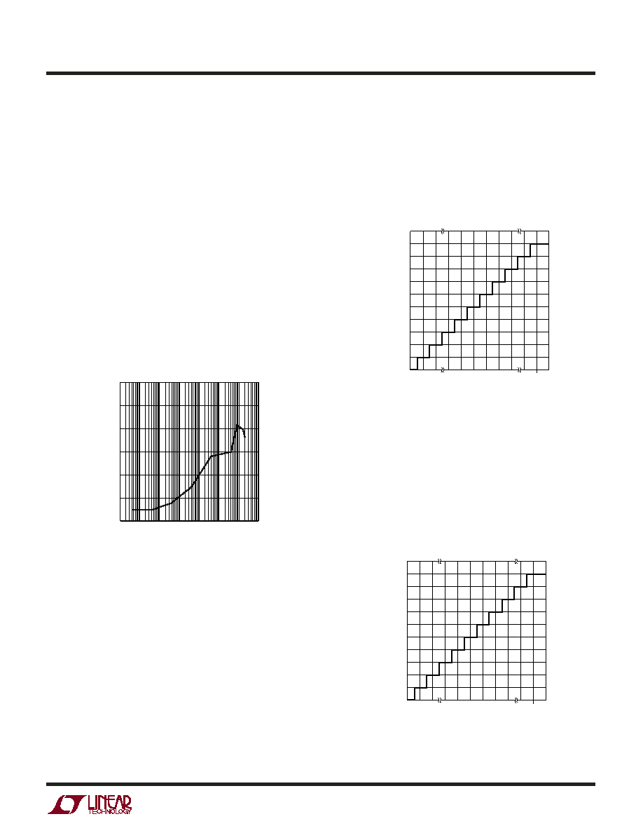
Figure 4 shows the ideal input/output characteristics for
the LTC1408-12 in unipolar mode (BIP = Low). The code
transitions occur midway between successive integer LSB
values (i.e., 0.5LSB, 1.5LSB, 2.5LSB, FS – 1.5LSB). The
output code is straight binary with 1LSB = 2.5V/4096 =
610
V for the LTC1408-12. The LTC1408-12 has 0.2 LSB
RMS of Gaussian white noise.
INPUT SPAN VERSUS REFERENCE VOLTAGE
The differential input range has a unipolar voltage span
that equals the difference between the voltage at the
reference buffer output VREF (Pin 23) and the voltage at
ground. The differential input range of the ADC is 0V to
2.5V when using the internal reference. The internal ADC
is referenced to these two nodes. This relationship also
holds true with an external reference.
DIFFERENTIAL INPUTS
The ADC will always convert the difference of CH+ minus
CH–, independent of the common mode voltage at any pair
of inputs. The common mode rejection holds up at high
frequencies (see Figure 3.) The only requirement is that
both inputs not go below ground or exceed VDD.
Figure 3. CMRR vs Frequency
1408 G11
FREQUENCY (Hz)
–100
CMRR
(dB)
–60
–20
–40
–80
0
10k
100k
1M
10M 100M 1G
–120
100
1k
Integral nonlinearity errors (INL) and differential nonlin-
earity errors (DNL) are largely independent of the common
mode voltage. However, the offset error will vary. DC
CMRR is typically better than –90dB.
Figure 5 shows the ideal input/output characteristics for
the LTC1408-12 in bipolar mode (BIP = High). The code
transitions occur midway between successive integer LSB
values (i.e., 0.5LSB, 1.5LSB, 2.5LSB, FS – 1.5LSB). The
output code is 2’s complement with 1LSB = 2.5V/4096 =
610
V for the LTC1408-12. The LTC1408-12 has 0.2 LSB
RMS of Gaussian white noise.
Figure 5. LTC1408-12 Transfer Characteristic
in Bipolar Mode (BIP = High)
INPUT VOLTAGE (V)
2'S
COMPLEMENT
OUTPUT
CODE
1408 F05
011...111
011...110
011...101
100...000
100...001
100...010
FS – 1LSB
–FS
Figure 4. LTC1408-12 Transfer Characteristic
in Unipolar Mode (BIP = Low)
INPUT VOLTAGE (V)
STRAIGHT
BINARY
OUTPUT
CODE
1408 F04
111...111
111...110
111...101
000...000
000...001
000...010
FS – 1LSB
0
发布紧急采购,3分钟左右您将得到回复。
相关PDF资料
LTC1408IUH#TRPBF
IC ADC 14BIT 600KSPS 32-QFN
LTC1409IG#TR
IC ADC 12BIT 800KSPS SMPL 28SSOP
LTC1410IG#TR
IC ADC 12BIT 1.25MSPS SMP 28SSOP
LTC1411IG#TRPBF
IC A/D CONV 14BIT 2.5MSPS 36SSOP
LTC1412IG#TR
IC ADC 12BIT 3MSPS SAMPLE 28SSOP
LTC1414IGN#TRPBF
IC A/D CONV 14BIT SAMPLNG 28SSOP
LTC1415CG#TRPBF
IC A/D CONV 12BIT SAMPLNG 28SSOP
LTC1416IG#TR
IC ADC 14BIT 400KSPS SMPL 28SSOP
相关代理商/技术参数
LTC1409CG
功能描述:IC A/D CONV 12BIT SAMPLNG 28SSOP RoHS:否 类别:集成电路 (IC) >> 数据采集 - 模数转换器 系列:- 标准包装:1,000 系列:- 位数:12 采样率(每秒):300k 数据接口:并联 转换器数目:1 功率耗散(最大):75mW 电压电源:单电源 工作温度:0°C ~ 70°C 安装类型:表面贴装 封装/外壳:24-SOIC(0.295",7.50mm 宽) 供应商设备封装:24-SOIC 包装:带卷 (TR) 输入数目和类型:1 个单端,单极;1 个单端,双极
LTC1409CG#PBF
功能描述:IC A/D CONV 12BIT SAMPLNG 28SSOP RoHS:是 类别:集成电路 (IC) >> 数据采集 - 模数转换器 系列:- 标准包装:1,000 系列:- 位数:12 采样率(每秒):300k 数据接口:并联 转换器数目:1 功率耗散(最大):75mW 电压电源:单电源 工作温度:0°C ~ 70°C 安装类型:表面贴装 封装/外壳:24-SOIC(0.295",7.50mm 宽) 供应商设备封装:24-SOIC 包装:带卷 (TR) 输入数目和类型:1 个单端,单极;1 个单端,双极
LTC1409CG#TR
功能描述:IC ADC 12BIT 800KSPS SMPL 28SSOP RoHS:否 类别:集成电路 (IC) >> 数据采集 - 模数转换器 系列:- 标准包装:1,000 系列:- 位数:12 采样率(每秒):300k 数据接口:并联 转换器数目:1 功率耗散(最大):75mW 电压电源:单电源 工作温度:0°C ~ 70°C 安装类型:表面贴装 封装/外壳:24-SOIC(0.295",7.50mm 宽) 供应商设备封装:24-SOIC 包装:带卷 (TR) 输入数目和类型:1 个单端,单极;1 个单端,双极
LTC1409CG#TRPBF
功能描述:IC A/D CONV 12BIT SAMPLNG 28SSOP RoHS:是 类别:集成电路 (IC) >> 数据采集 - 模数转换器 系列:- 标准包装:1,000 系列:- 位数:12 采样率(每秒):300k 数据接口:并联 转换器数目:1 功率耗散(最大):75mW 电压电源:单电源 工作温度:0°C ~ 70°C 安装类型:表面贴装 封装/外壳:24-SOIC(0.295",7.50mm 宽) 供应商设备封装:24-SOIC 包装:带卷 (TR) 输入数目和类型:1 个单端,单极;1 个单端,双极
LTC1409CSW
功能描述:IC A/D CONV 12BIT SAMPLNG 28SOIC RoHS:否 类别:集成电路 (IC) >> 数据采集 - 模数转换器 系列:- 标准包装:1,000 系列:- 位数:12 采样率(每秒):300k 数据接口:并联 转换器数目:1 功率耗散(最大):75mW 电压电源:单电源 工作温度:0°C ~ 70°C 安装类型:表面贴装 封装/外壳:24-SOIC(0.295",7.50mm 宽) 供应商设备封装:24-SOIC 包装:带卷 (TR) 输入数目和类型:1 个单端,单极;1 个单端,双极
LTC1409CSW#PBF
功能描述:IC A/D CONV 12BIT SAMPLNG 28SOIC RoHS:是 类别:集成电路 (IC) >> 数据采集 - 模数转换器 系列:- 标准包装:1,000 系列:- 位数:12 采样率(每秒):300k 数据接口:并联 转换器数目:1 功率耗散(最大):75mW 电压电源:单电源 工作温度:0°C ~ 70°C 安装类型:表面贴装 封装/外壳:24-SOIC(0.295",7.50mm 宽) 供应商设备封装:24-SOIC 包装:带卷 (TR) 输入数目和类型:1 个单端,单极;1 个单端,双极
LTC1409CSW#TR
功能描述:IC ADC 12BIT 800KSPS SMPL 28SOIC RoHS:否 类别:集成电路 (IC) >> 数据采集 - 模数转换器 系列:- 标准包装:1,000 系列:- 位数:12 采样率(每秒):300k 数据接口:并联 转换器数目:1 功率耗散(最大):75mW 电压电源:单电源 工作温度:0°C ~ 70°C 安装类型:表面贴装 封装/外壳:24-SOIC(0.295",7.50mm 宽) 供应商设备封装:24-SOIC 包装:带卷 (TR) 输入数目和类型:1 个单端,单极;1 个单端,双极
LTC1409CSW#TRPBF
功能描述:IC A/D CONV 12BIT SAMPLNG 28SOIC RoHS:是 类别:集成电路 (IC) >> 数据采集 - 模数转换器 系列:- 标准包装:1,000 系列:- 位数:12 采样率(每秒):300k 数据接口:并联 转换器数目:1 功率耗散(最大):75mW 电压电源:单电源 工作温度:0°C ~ 70°C 安装类型:表面贴装 封装/外壳:24-SOIC(0.295",7.50mm 宽) 供应商设备封装:24-SOIC 包装:带卷 (TR) 输入数目和类型:1 个单端,单极;1 个单端,双极